|
|
|
Inventor
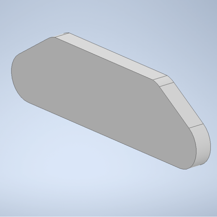
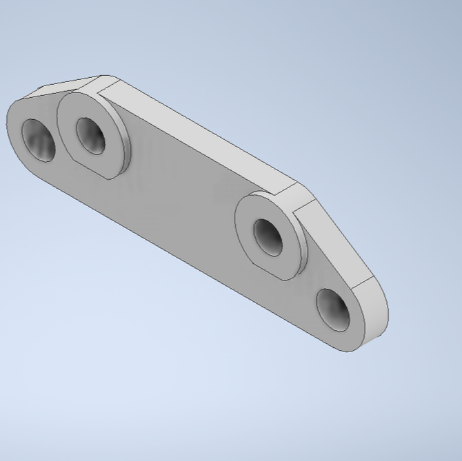
As for the top left picture, I started with a rectangle, putting four circles in it. After trimming the rectangle, we were able to come out with the curved shape of the bracket. After extruding it, were completed the first step of the break bracket. The middle picture is the second step. For this we went into our second sketch and added two circles. Then we put a line through the circles and trimmed it in order to get that straight part of the circle. After also extruding this sketch, we were done designing it in Inventor!
|
|
|
|
Fusion 360 and Setup
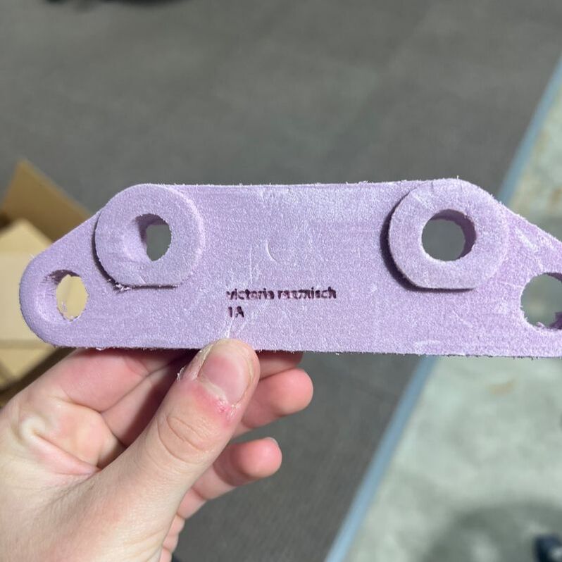
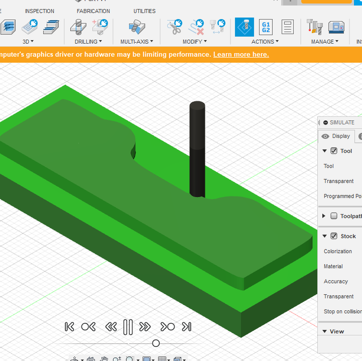
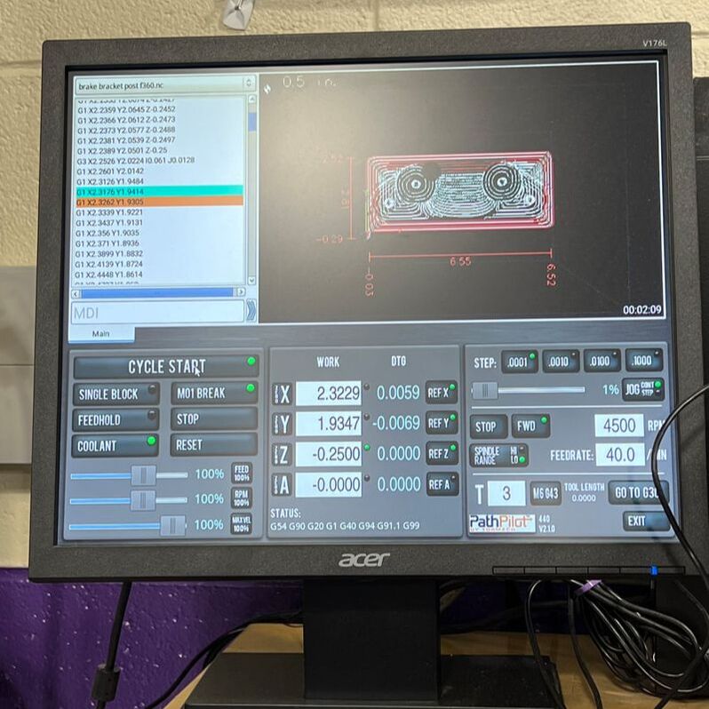
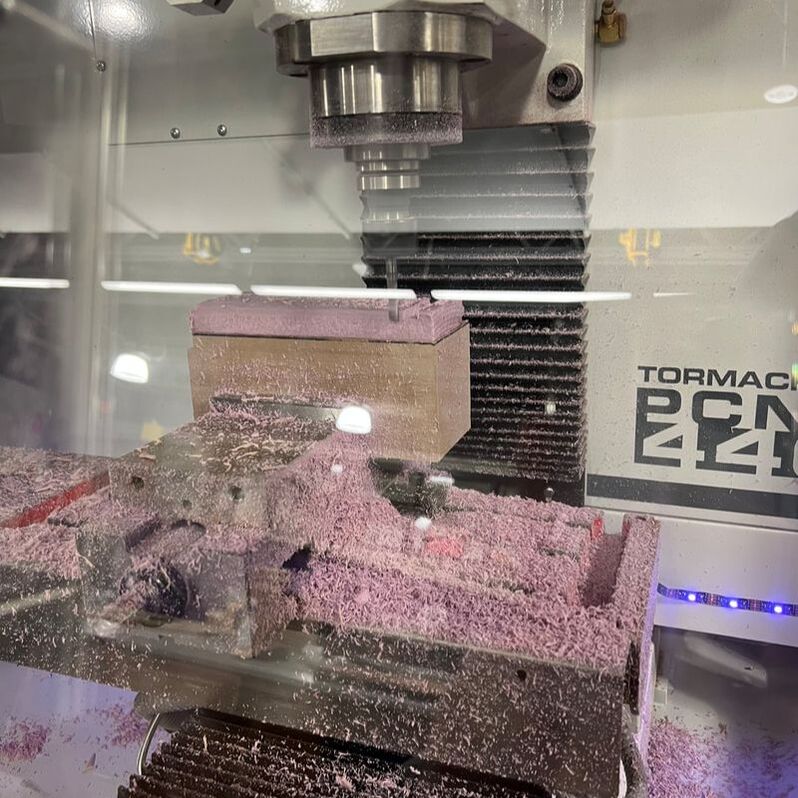
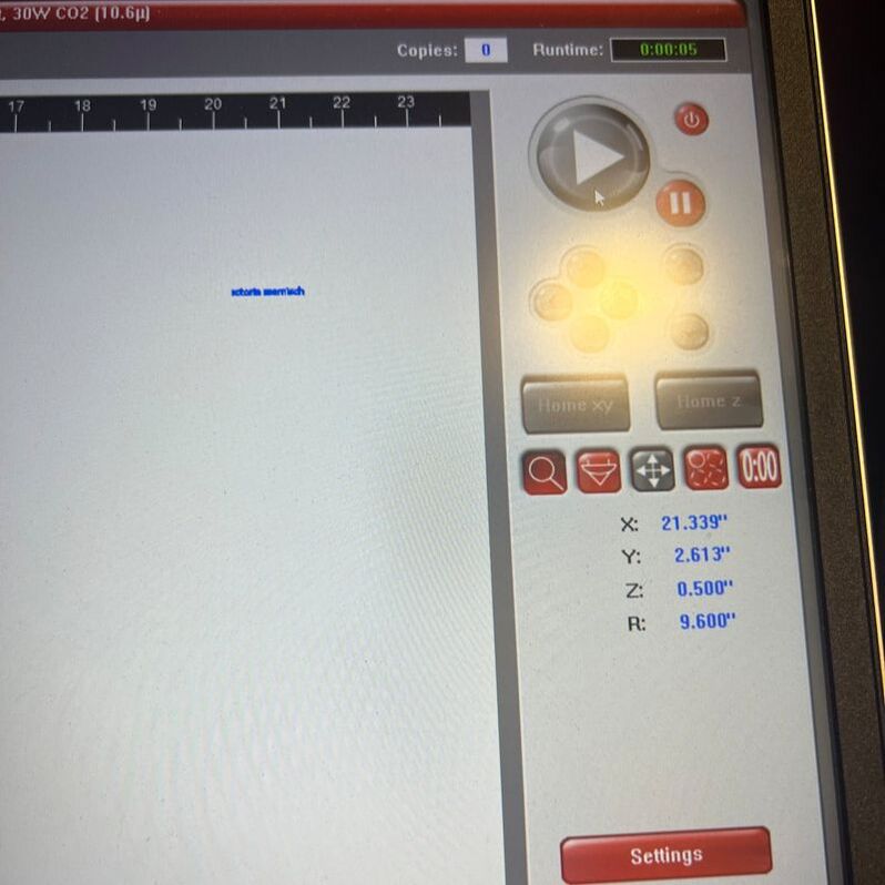
The top left picture is from Fusion 360, where I setup my toolpath for my bracket. Once I had everything set up, I then saved it to my flash drive and started on the mill. After setting all my axis to zero, and putting my foam in the mill, I was ready to start. Finally, I added my name to the bracket using illustrator. The final product is the very top right picture.
What I learned
Over the course of this project, I learned how to operate fusion 360, what what it is used for. Fusion 360 is specifically used for manufacturing and engineering projects. You can also see how exactly the machine you are using will work on the material. For example, it shows you the starting point of where it will start drilling, and take you through the whole process of cutting out your part. Aside from fusion, I learned how to use the mill and what to expect with it. I discovered it to be fairly easy to use, as long as you set it at the right starting point. Overall this project introduced me to both Fusion 360 and the mill machine.
